Why I'm Building a Distortion Pedal
I was blown away, when I got my first serious practice amp–a Blackstar ID:Core 40. Out-of-the-box it came with five distinct voices from Clean to Crunch with some nice overdrive-options in between. I spent countless hours twisting the tone knobs and cycling through presets chasing the perfect distortion sound I heard in my head but couldn't quite capture.
Even after dialing in what seemed like a great tone, I found something was always missing: it either lacked punch, felt too compressed or just did not sound right in the mix. This inconsistency sparked my curiosity. As a mechanical engineering student, I understood how small tweaks in a mechanical system can yield big differences in system performance. I knew this principle also had to apply to my guitar tone.
By building my own distortion circuit, I could tweak the components of the system and their connections to create the exact tone I had been chasing. No longer would I be limited by fixed diode thresholds or fixed filtering frequencies—instead, I could choose exatly how the signal is shaped.
This series will be a guided tour through the pedal. We'll dissect each stage of the signal chain and discuss how it works and which design choices have been made. Along the way you'll encounter:
-
KiCad Simulations showing how the signal behaves in the circuit in theory, including waveform snapshots at different points and frequency response plots of various tone-stack configurations
-
Audio Demos, which allow you to hear the differences between the signal at different points in the circuit
-
Interactive components that let you interact with the circuit and modify it on your own.
Think of it as an engineer's tour of the circuit: annotated schematics, animated simulations and hands-on KiCad models that let you experiment in-browser. Whether you're purely curious about electronics or eager to build your own pedal, this series will equip you with both practical and theoretical insight.
What is a distortion Pedal?
Electric guitars produce a smal, alternating current proportional to the vibrations of the strings. A distortion pedal amplifies the signal beyond a diode or transistor's foward threshold, deliberately "overdriving" the waveform so it clips— flattening peaks and generating new harmonics. These harmics add grit, sustain and character to the sound.
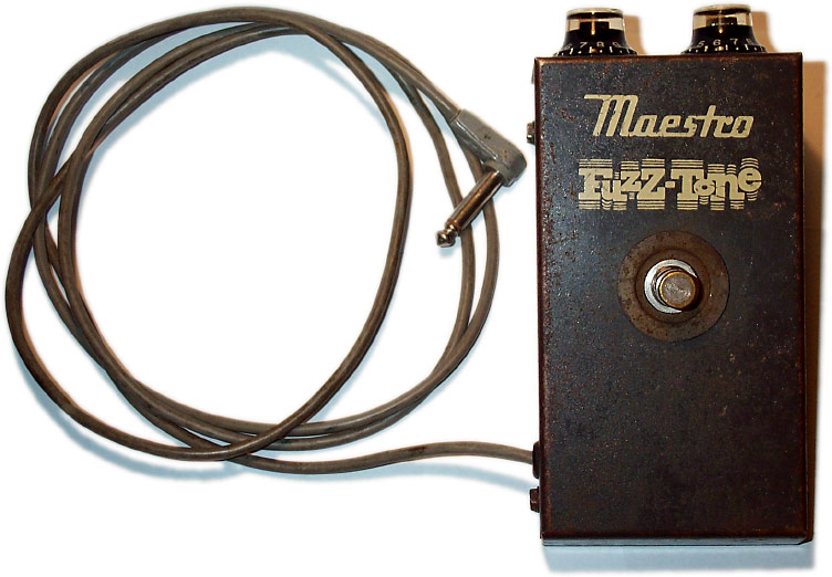
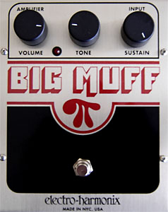
In 1964, Dave Davies of The Kinks famously slit the cone of his speaker cabinet with a razor blade to rough up its edges, thus creating the beloved tone on You Really Got Me. Shortly after, Keith Richards' prominent use of a Maestro FZ-1 Fuzz-Tone pedal on Satisfaction led to a surge in sales for the pedal. This prompted other companies to also start developing distortion pedals and shortly after famous pedals such as the Fuzz Face and the Big Muff Pi saw the light of day.
Commonly found in modern pedals are one (or more) of three types of diodes:
- Silicon diodes (Vf ≈ 0.7 V): Hard clipping, tight attack, plenty of upper harmonics.
- Germanium diodes (Vf ≈ 0.3 V): Softer threshols, smoother clipping, warmer fuzz.
- LED's (Vf ≈ 1.8-2 V): Very soft clipping, subtle saturation, higher headroom.
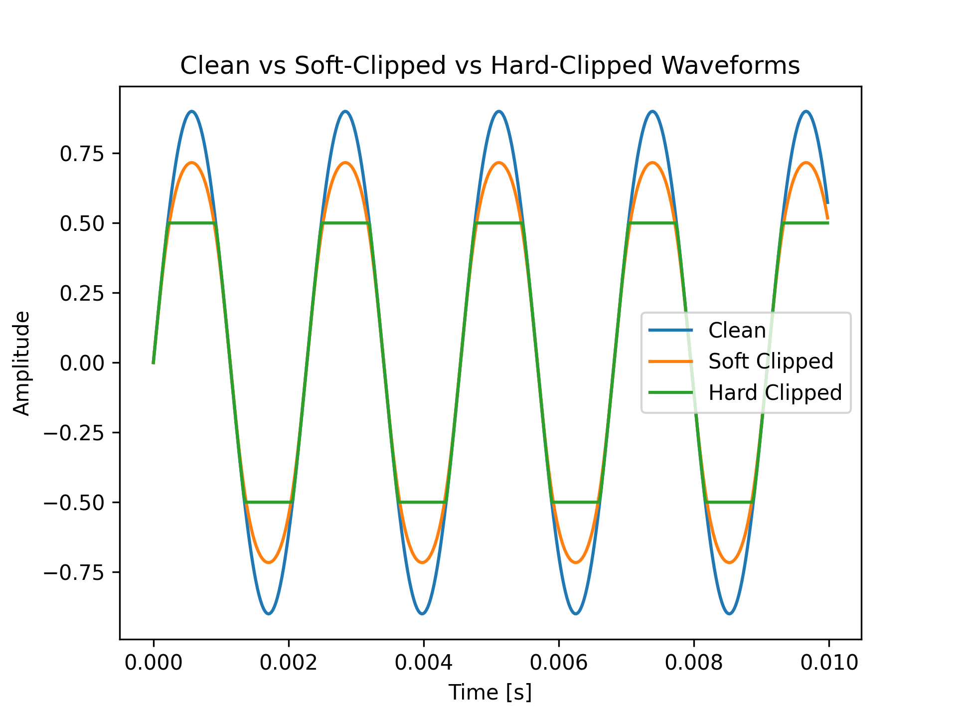
Below is a small diagram showing a clean, unclipped sine wave and that same wave with two levels of clipping. Notice how the peaks flatten as clipping increases (for example, by choosing diodes with lower forward voltage). To the right, you can listen to three short audio samples of a clean, soft-clipped, and hard-clipped guitar signal (Check your volume before playing if you are wearing headphones).
A very high level overview of the schematic
Here's a simplified block diagram of full pedal circuit. Dont worry if it looks comples—we'll break down every stage in future posts.

Above you see a block diagram of the circuit I am going to be building. It might look a bit daunting at first so I'll slowly go through what happens at each part.
-
Input Buffer — This is the entry point of the guitar signal. It is designed to have a very high impedance to avoid overworking the pickups of the guitar (I'll go through this more in a later post, but impedance is basically the equivalent of electrical resistance for guitar-signals).
-
First Gain & Clipping Stage — The first of two gain/clipping stages. Here the signal is amplified and clipped by silicon diodes. This build-up of this stage is similar to core circuitry from the famous Ibanez Tube Screamer and the hope is that this stage will also be able to at least sort of mimic a Tube Screamer.
-
Voicing Filter — This is an adjustable filter where some of the bass can be cut before the second and harder gain stage. The amount of bass that is cut is controlled by a knob.
-
Second Gain & Clipping Stage — Here the signal is, once again, amplified and then clipped by diodes. Here, however, two switches are implemented before the diodes which lets the user switch between 5 diode pairs and 3 clipping options with the flick of a button.
-
Clean Blend — Here the signal can be mixed with some of the undistorted signal from the guitar to bring back some definition, especially for high-gain settings.
-
Tilt EQ — This is an active tilt network that either boosts bass and cuts treble or vice versa.
-
Output Buffer & Bypass — The output buffer is designed to have a low impedance so that the signal is ready to either go through another pedal or go into an amplifier. The pedal will also implement a buffered bypass switch.
This circuit is more elaborate than your average distortion pedal—maybe even more complex than necessary. However, a lot of effort has been put into making sure that each part of the pedal only "does one thing" so to say. Hopefully this means that even with a complex circuit and a lot of knobs that can be adjusted, I am still able to sculpt all the tones I am seeking.
What to Expect from This Series
This series is going to be a deep dive into each part of the above block diagram. The future more 'theoretical' posts will include small animations and interactive simulations that can help you understand all of the choices that have been made. I will also make circuit simulations using KiCad to confirm that the circuit is behaving as expected in theory and include simulated audio snippets so that you can hear how the guitar signal might sound at each stage.
I am going to be talking about both the electrical engineering aspects of designing the circuit and choosing the correct components, but I'll also be talking about the other miscellaneous things one has to devote time to when building a pedal, such as soldering and designing an enclosure (the focus will however be on the more electrical side of things).
I will provide the entire schematics for the pedal once the series is finished along with any other files I have for the project (e.g. 3D print-files). Also I will keep track of exactly how much I am going to be spending on building the pedal so you can get an idea about how easily you can get started yourself.
I’m also setting up a mailing list to notify you about new posts, demos, and code releases. If you’re interested in receiving interactive updates as soon as they go live, let me know and I can provide sign‑up details in the next post.
If there are any specific audio, visual, or interactive demos that would clarify any stage please do not hesitate to contact me and I will work on getting it implemented.